


- When designing a ±12V isolated power supply using the STMicroelectronics SG3524N, what are the critical considerations for the transformer winding ratio and the external transistor selection to ensure stable dual-output regulation?
- For a ±12V isolated power supply with the SG3524N, the transformer winding ratio is crucial. You'll need to calculate the required primary to secondary turns ratio considering the input voltage range (8V-40V), the desired output voltage (12V and -12V), and the maximum duty cycle (45%) of the SG3524N. A typical approach involves designing for the lowest input voltage and highest load to determine the minimum duty cycle required to achieve the desired output. For the external transistor selection, choose high-current NPN or PNP transistors (depending on your topology, e.g., push-pull or half-bridge for the positive output, and potentially a complementary pair or dedicated driver for the negative rail, though the SG3524N primarily drives the positive side's output transistors) with sufficient voltage and current ratings to handle the peak transistor currents, which will be higher than the average output current due to the switching nature. Ensure adequate heat sinking for these external components as they will dissipate significant power. The SG3524N's output configuration is a transistor driver, meaning it provides the drive signal for external switching elements, and proper biasing of these elements is essential for efficient operation.
- Can the STMicroelectronics SG3524N be reliably used in a flyback converter for battery-powered medical equipment operating in an industrial environment where ambient temperatures can fluctuate between 0°C and 70°C, and what are the long-term reliability concerns?
- Yes, the STMicroelectronics SG3524N can be used in a flyback converter for battery-powered medical equipment operating within its specified ambient temperature range of 0°C to 70°C. However, for long-term reliability in industrial environments, it's critical to consider the thermal management of the entire power supply. Ensure that the SG3524N itself, along with any external components like power MOSFETs, diodes, and inductors, are adequately derated for continuous operation at the higher end of the temperature range. Evaluate the impact of temperature on the capacitance of electrolytic capacitors, which are often used in power supplies, as their lifespan can be significantly reduced at elevated temperatures. Furthermore, consider shielding the device and the surrounding circuitry from electromagnetic interference (EMI) common in industrial settings. The SG3524N has a relatively high voltage supply range (8V-40V), which offers some robustness against voltage fluctuations.
- I'm migrating a legacy design that used a different push-pull controller. What are the key electrical differences and potential integration challenges when replacing it with the STMicroelectronics SG3524N, especially regarding its 300kHz switching frequency and 45% maximum duty cycle?
- When migrating from a legacy push-pull controller to the STMicroelectronics SG3524N, several key electrical differences and integration challenges need to be addressed. The SG3524N's fixed switching frequency of 300kHz is a significant factor. Ensure your transformer's core material and size are optimized for this frequency to avoid saturation and excessive core losses. The maximum duty cycle of 45% for the SG3524N implies that the transformer's primary winding inductance and the input voltage must be carefully selected to prevent over-driving the output transistors and exceeding this limit, especially under light load conditions or with voltage dips. The SG3524N's output configuration is a transistor driver; confirm if your legacy controller had similar drive characteristics or if external driver circuitry will be needed. Also, verify the control loop compensation network, as the SG3524N's internal compensation characteristics might differ from your original controller, potentially requiring adjustments to maintain stability.
- For a compact step-up/step-down DC-DC converter in a portable application, what are the trade-offs and limitations of using the STMicroelectronics SG3524N's internal transistor driver for the switching elements compared to using an external gate driver IC?
- Using the STMicroelectronics SG3524N's internal transistor driver for switching elements in a compact portable application offers simplicity and reduced component count. However, the trade-offs and limitations are primarily related to the drive strength and switching speed. The internal driver is designed to drive moderately sized power MOSFETs or BJTs. For higher current applications or when faster switching speeds are required to minimize switching losses and improve efficiency, an external gate driver IC would be superior. External drivers can provide higher peak currents to charge and discharge the gate capacitance of power MOSFETs more quickly, leading to reduced switching times and lower power dissipation. Furthermore, external drivers often offer features like desaturation detection and under-voltage lockout that enhance protection and reliability. The SG3524N's maximum duty cycle of 45% and its 300kHz switching frequency may also limit the performance gains achievable with an external driver if the overall system design is constrained by other factors.
- What are the implications of the STMicroelectronics SG3524N's "No" for Clock Sync on system design when multiple power supplies are required to operate in close proximity, and how can potential interference be mitigated?
- The STMicroelectronics SG3524N's "No" for Clock Sync means that each SG3524N will operate independently with its own internal oscillator, potentially leading to asynchronous switching frequencies if multiple devices are used in close proximity. This lack of synchronization can result in beat frequencies and increased electromagnetic interference (EMI), which can be detrimental in sensitive applications. To mitigate this, consider physically separating the SG3524N units and their associated magnetics to minimize inductive and capacitive coupling. Employ thorough filtering on input and output lines, and consider using shielding for the power supply modules. If precise synchronization is critical, an external synchronization circuit might be necessary, where a master clock signal is distributed to all SG3524N units, though this would add complexity. Alternatively, if a fixed frequency is acceptable, you might consider if the 300kHz switching frequency is sufficiently high to push noise into less critical bands, or investigate if external components can help spread the noise spectrum.
- When considering the STMicroelectronics SG3524N for a 24V to 5V step-down converter application, what are the key concerns regarding output ripple voltage and transient response, given its 45% maximum duty cycle and 300kHz switching frequency?
- When designing a 24V to 5V step-down converter with the STMicroelectronics SG3524N, the output ripple voltage and transient response are primarily influenced by the output filter design, which typically involves an inductor and capacitors. The 300kHz switching frequency of the SG3524N allows for smaller inductor and capacitor values compared to lower frequency controllers, which can help in reducing the physical size of the power supply. However, to achieve a low output ripple voltage, the inductor's ripple current and the equivalent series resistance (ESR) of the output capacitors become critical. For transient response, the bandwidth of the control loop and the capacitor selection play a significant role. The 45% maximum duty cycle limitation of the SG3524N means that under heavy load transients, the controller might not be able to respond quickly enough if the input voltage drops, potentially leading to temporary output voltage sags. Careful selection of external components and control loop compensation is essential to meet ripple and transient specifications.
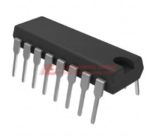
- I'm replacing a failed Texas Instruments SG3524 with an STMicroelectronics SG3524N. Are there any pinout compatibility issues or significant performance differences I should be aware of in a standard 16-DIP package for my existing circuit?
- While the STMicroelectronics SG3524N shares the base part number SG3524, it's crucial to verify exact pinout compatibility and potential performance differences when replacing a Texas Instruments SG3524. Although both are typically supplied in a 16-DIP package, subtle variations in internal circuitry, especially related to output drive characteristics or internal reference voltages, might exist. Always consult the datasheets for both the specific Texas Instruments SG3524 you are replacing and the STMicroelectronics SG3524N. Pay close attention to the specified operating voltage ranges (8V-40V for the SG3524N), output current capabilities of the internal drivers, and any recommended external component values. While the core functionality is likely the same, minor differences in switching characteristics or transient response could necessitate minor adjustments to your control loop compensation or external component values for optimal performance and stability. The STMicroelectronics SG3524N specifies a 0°C to 70°C operating temperature, so ensure this aligns with your application's environmental requirements.