Choose your country or region.

74F1071MTCX.jpg ImageView larger image
Image may be representation.
See specs for product details.

UCC28070QPWRQ1

In Stock 1350 pcs Reference Price(In US Dollars)
1+
$1.5932
Manufacturer Part Number:
UCC28070QPWRQ1
Manufacturer / Brand
Texas Instruments
Part of Description:
IC PFC CTL CCM ADJUSTABL 20TSSOP
Datasheets:
UCC28070QPWRQ1(1).pdfUCC28070QPWRQ1(2).pdf
Lead Free Status / RoHS Status:
ROHS3 Compliant
Stock Condition:
New original, 1350 pcs Stock Available.
ECAD Model:
Ship From:
Hong Kong
Shipment Way:
DHL/Fedex/TNT/UPS

Inquiry Online

Please complete all required fields with your contact information.Click "SUBMIT REQUEST" we will contact you shortly by email. Or Email us: Info@IC-Components.com
Part Number
Manufacturer
Require Quantity
Target Price(USD)
Company Name
Contact Name
E-mail
Phone
Message
Please enter Verify Code and click "Submit"
Part Number UCC28070QPWRQ1
Manufacturer / Brand Texas Instruments
Stock Quantity 1350 pcs Stock
Category Integrated Circuits (ICs) > Power Management (PMIC) - PFC (Power Factor Correction)
Description IC PFC CTL CCM ADJUSTABL 20TSSOP
Lead Free Status / RoHS Status: ROHS3 Compliant
RFQ UCC28070QPWRQ1 Datasheets UCC28070QPWRQ1 Details PDF
UCC28070QPWRQ1 Details PDF for KR.pdf
UCC28070QPWRQ1 Details PDF for ES.pdf
UCC28070QPWRQ1 Details PDF for DE.pdf
UCC28070QPWRQ1 Details PDF for FR.pdf
UCC28070QPWRQ1 Details PDF for IT.pdf
Voltage - Supply 11.2V ~ 21V
Supplier Device Package 20-TSSOP
Series Automotive, AEC-Q100
Package / Case 20-TSSOP (0.173', 4.40mm Width)
Package Tape & Reel (TR)
Operating Temperature -40°C ~ 125°C
Mounting Type Surface Mount
Mode Continuous Conduction (CCM)
Frequency - Switching Adjustable
Current - Startup 20 mA
Base Product Number UCC28070

Packaging & ESD

Industry-standard static shielding packaging is used for electronic components.Anti-static, light-transparent materials allow easy identification of ICs and PCB assemblies.
The packaging structure provides electrostatic protection based on Faraday cage principles.This helps protect sensitive components from static discharge during handling and transportation.


All products are packed in ESD-safe anti-static packaging. Outer packaging labels include part number, brand, and quantity for clear identification. Goods are inspected prior to shipment to ensure proper condition and authenticity.

ESD protection is maintained throughout packing, handling, and global transportation. Secure packaging provides reliable sealing and resistance during transit. Additional cushioning materials are applied when required to protect sensitive components.

QC(Part Testing by IC Components)Quality Warranty

We can offer worldwide express delivery service, such as DHLor FedEx or TNT or UPS or other forwarder for shipment.

Global Shipment by DHL/FedEx/TNT/UPS

Shipping Fees reference DHL/FedEx
1). You can offer your express delivery account for shipment, ifyou haven’t any express account for shipment, we can offer our account inadvance.
2). Use our account for shipment, Shipment charges(Reference DHL/FedEx, Different Countries has different price.)
Shipment charges: (Reference DHL and FedEX)
Weight(KG): 0.00kg-1.00kg Price(USD$) : USD$60.00
Weight(KG): 1.00kg-2.00kg Price(USD$) : USD$80.00
* The price of cost is reference with DHL/FedEx. The detail charges, please contact us. Different country the express charges are different.


We accept the payment terms: Telegraphic Transfer(T/T), Credit Card, PayPal and Western Union.

PayPal:

PayPal Bank Information:
Company Name : IC COMPONENTS LTD
Paypal ID: PayPal@IC-Components.com

BANK TRANSFAR (Telegraphic Transfer)

Payment For Telegraphic Transfers:
Company Name : IC COMPONENTS LTD Beneficiary Account Number : 549-100669-701
Beneficiary Bank name : Bank of Communications (Hong Kong) Ltd Beneficiary Bank Code : 382 (for local payment)
Beneficiary Bank SWIFT : COMMHKHK
Beneficiary Bank Address : Tsuen Wan Market Street Branch 53 Market Street, Tsuen Wan N.T., Hong Kong

Any inquires or questions, please kindly contact us Email: Info@IC-Components.com


UCC28070QPWRQ1 Product Details:

The UCC28070QPWRQ1 is a high-performance Power Factor Correction (PFC) Integrated Circuit (IC) manufactured by Luminary Micro / Texas Instruments. This device is designed to address power conversion challenges, specifically in applications that require continuous conduction mode (CCM) PFC functionality.

The UCC28070QPWRQ1 is part of the Automotive, AEC-Q100 series, ensuring its reliability and suitability for use in automotive and other demanding applications. It operates within a wide temperature range of -40°C to 125°C, making it versatile for diverse environmental conditions.

Key features of the UCC28070QPWRQ1 include its adjustable switching frequency, which allows for optimization of the PFC stage, and its continuous conduction mode (CCM) operation, which enables improved power conversion efficiency and reduced electromagnetic interference (EMI). The device has a startup current of 20mA and can operate with a supply voltage range of 11.2V to 21V, providing flexibility for various power supply configurations.

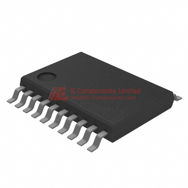
The UCC28070QPWRQ1 is packaged in a space-efficient 20-TSSOP (Thin Shrink Small Outline Package) enclosure, which simplifies board layout and integration. The device is also RoHS-compliant, ensuring environmental-friendliness.

The UCC28070QPWRQ1 is primarily used in power conversion applications, such as AC-DC power supplies, battery chargers, and industrial power supplies, where high power factor and efficient energy conversion are crucial. Its adjustable switching frequency and CCM operation make it well-suited for a wide range of power ratings and topologies.

Equivalent or alternative models to the UCC28070QPWRQ1 include the UCC28070-Q1, which is a qualified version for automotive applications, and the UCC28070, which is the commercial version of the device. These models offer similar functionality and specifications, allowing designers to select the most appropriate option for their specific application requirements.

UCC28070QPWRQ1 Key Technical Attributes

Manufacturer Part Number: UCC28070QPWRQ1

Manufacturer: Luminary Micro / Texas Instruments

Main Category: Integrated Circuits (ICs)

Small Classification: PMIC - PFC (Power Factor Correction)

UCC28070QPWRQ1 Packing Size

Package Type: 20-TSSOP

Material: High Reliability Plastic

Package Size: 20-TSSOP (0.173", 4.40mm Width)

Thermal Characteristics: Moisture Sensitivity Level (MSL) 1 (Unlimited)

Electrical Properties: Voltage - Supply: 11.2 V ~ 21 V

UCC28070QPWRQ1 Application

The UCC28070QPWRQ1 is specifically designed for applications requiring high-efficiency power factor correction. Ideal for automotive applications, especially considering its compliance with AEC-Q100 standards, this component ensures optimal performance in environments that require durable and reliable power management solutions.

UCC28070QPWRQ1 Features

The UCC28070QPWRQ1, part of Texas Instruments' power management ICs, utilizes Continuous Conduction Mode (CCM) to improve the power factor of AC input systems. It supports a variable switching frequency and a startup current of merely 20mA, making it highly efficient for automotive applications. The adjustable features allow system designers to fine-tune its performance according to specific demands, enhancing overall system integrity and energy usage.

UCC28070QPWRQ1 Quality and Safety Features

This Texas Instruments product adheres to RoHS compliance, ensuring it is manufactured lead-free and maintains high safety and environmental standards. The device’s reliability is further certified by its Listing under AEC-Q100, indicative of its robustness and suitability for the strenuous automotive environment.

UCC28070QPWRQ1 Compatibility

Designed for broad compatibility across automotive power systems, the UCC28070QPWRQ1 works efficiently within a voltage supply range of 11.2 V to 21 V. Its surface mount design in a 20-TSSOP package allows for versatile PCB (Printed Circuit Board) placement and is optimal for streamlined system integration.

UCC28070QPWRQ1 Datasheet PDF

For the most detailed and authoritative information on the UCC28070QPWRQ1, including full specifications, diagrams, and application notes, please download the datasheet available on our webpage. It provides comprehensive insights useful for engineers and professionals looking to integrate this IC into their projects.

Quality Distributor

As a leading distributor for Texas Instruments, IC-Components guarantees premium-quality sourcing of the UCC28070QPWRQ1. Extensive stock, global delivery, and expert support mark our service. For accurate quotes and reliable order fulfilment specializing in semiconductor components, consider IC-Components as your go-to distributor partner. Visit our website today to receive a custom quote and browse our extensive inventory of high-quality parts.

Frequently Asked Questions

What are the key design considerations when integrating the UCC28070QPWRQ1 into a high-reliability automotive power supply system, and how does its AEC-Q100 qualification impact component selection?
The UCC28070QPWRQ1 is qualified to AEC-Q100 Grade 1 standards, making it suitable for automotive applications where extended temperature operation (-40°C to 125°C) and long-term reliability are critical. Designers must ensure that the surrounding passive components, such as input capacitors and current sense resistors, are also rated for automotive-grade temperatures and vibration profiles. Additionally, the device’s 11.2 V to 21 V supply voltage range requires careful attention to transient protection on the VCC rail, especially in 12 V and 24 V vehicle systems where load dump events can exceed 40 V. Proper PCB layout with minimized high-current loop areas and thermal vias under the TSSOP20 package is essential to maintain stable operation and meet EMI requirements.
Can the UCC28070QPWRQ1 be used in discontinuous conduction mode (DCM), and what are the implications if a design inadvertently operates near the DCM boundary?
The UCC28070QPWRQ1 is specifically designed for continuous conduction mode (CCM) operation and does not support DCM. Operating near the DCM boundary—such as at very light loads or with undersized inductors—can lead to subharmonic oscillation, increased current stress, and degraded power factor. Engineers should ensure that the minimum load current remains above the critical threshold defined by the inductor value and switching frequency. For applications requiring wide load ranges, consider adding preload resistors or evaluating alternative PFC controllers with multimode operation, as the UCC28070QPWRQ1 lacks inherent DCM detection or mode transition logic.
What are the practical trade-offs when replacing a legacy analog PFC controller like the UC2854 with the UCC28070QPWRQ1 in an existing industrial power supply design?
Migrating from the UC2854 to the UCC28070QPWRQ1 offers improved efficiency and tighter regulation due to its digital-like control loop and integrated features such as input voltage feedforward and cycle-by-cycle current limiting. However, the UCC28070QPWRQ1 requires a higher minimum supply voltage (11.2 V vs. 10 V for UC2854), which may necessitate redesigning the startup circuit or bias supply. Additionally, the UCC28070QPWRQ1 uses a different pinout and control interface, requiring PCB layout changes. While both support CCM, the UCC28070QPWRQ1’s adjustable switching frequency and built-in soft-start reduce external component count but demand careful tuning of the compensation network for stability.
How should the switching frequency be selected and implemented when using the UCC28070QPWRQ1 in a compact SMPS design with tight EMI constraints?
The UCC28070QPWRQ1 allows adjustable switching frequency via an external resistor connected to the RT pin, typically ranging from 20 kHz to 200 kHz. For compact designs, higher frequencies reduce magnetic size but increase switching losses and EMI emissions. To balance size and compliance, select a frequency above 60 kHz to avoid audible noise while staying below 150 kHz to minimize high-frequency harmonics. Use a shielded inductor and place the frequency-setting resistor close to the IC to reduce parasitic coupling. Additionally, synchronize the frequency to the system’s main clock if possible, as the UCC28070QPWRQ1 supports external synchronization through the SYNC pin, reducing beat frequencies and simplifying EMI filtering.
What are the risks of using the UCC28070QPWRQ1 in a universal input (85–265 VAC) offline application without proper inrush current management?
The UCC28070QPWRQ1 controls the PFC stage but does not include inrush current limiting. In universal input applications, the bulk capacitor charging during startup can cause excessive peak currents that stress the rectifier bridge, input fuse, and relay contacts. Without an NTC thermistor or active inrush circuit, repeated power cycling may degrade system reliability. Designers must implement external inrush protection and ensure the startup current (typically 20 mA) is sufficient to charge the VCC capacitor quickly without triggering UVLO reset loops. The UCC28070QPWRQ1’s soft-start feature helps reduce inrush after initial power-up but does not mitigate the initial capacitor charging surge.
Is the UCC28070QPWRQ1 suitable for use in a three-phase PFC application, and what modifications would be required?
The UCC28070QPWRQ1 is a single-phase PFC controller and is not designed for direct use in three-phase systems. Applying it to a three-phase topology without phase interleaving or dedicated control per phase will result in unbalanced current sharing, poor power factor, and potential overcurrent conditions. For three-phase applications, consider using dedicated multiphase PFC controllers or multiple UCC28070QPWRQ1 devices with synchronized clocks and independent current loops. However, this increases complexity and cost. For high-power three-phase systems, TI offers specialized controllers like the UCD3138, which are better suited for digital multiphase PFC.
How does the moisture sensitivity level (MSL 1) of the UCC28070QPWRQ1 impact handling and storage in high-volume manufacturing environments?
The UCC28070QPWRQ1 is rated MSL 1 (unlimited floor life), meaning it can be exposed to ambient conditions (>30°C/60% RH) indefinitely without requiring dry packing or bake-out before reflow. This simplifies logistics and reduces handling costs in automotive and industrial production lines. However, standard ESD precautions still apply due to the device’s CMOS structure. Storing the Digi-Reel packaging in sealed antistatic bags with desiccant is recommended for long-term inventory, even though moisture absorption is not a concern. This rating ensures compatibility with just-in-time manufacturing workflows without additional preprocessing steps.
What are the critical layout guidelines for the current sense and gate drive traces when designing with the UCC28070QPWRQ1 to avoid noise-induced malfunctions?
The current sense input (ISENSE) on the UCC28070QPWRQ1 is highly sensitive to noise due to its high-gain error amplifier. Route the sense resistor connection using a Kelvin configuration with short, direct traces to pins 14 and 15, avoiding parallel runs with high di/dt gate drive lines. The gate drive outputs (GDA and GDB) should be routed with minimal length and separated from analog signals to prevent coupling. Use a solid ground plane beneath the IC and connect the exposed thermal pad to ground with multiple vias. Additionally, place the VCC bypass capacitor (0.1 µF ceramic) as close as possible to pin 1 and ground to suppress high-frequency oscillations during switching transitions.
Can the UCC28070QPWRQ1 be paralleled with another identical device to increase output power, and what synchronization challenges must be addressed?
While the UCC28070QPWRQ1 does not support direct current sharing or master-slave paralleling, two devices can be synchronized using the SYNC pin to reduce beat frequencies and simplify input filtering. However, each controller must drive its own power stage with independent current loops, as there is no built-in mechanism for load balancing. Mismatched component tolerances or layout asymmetries can lead to uneven power distribution and thermal stress. For scalable high-power designs, consider using a single higher-current PFC stage or migrating to a controller with dedicated multiphase support. Paralleling UCC28070QPWRQ1 devices is feasible only in applications where slight imbalance is acceptable and synchronization is carefully implemented.
What alternatives should be considered if the UCC28070QPWRQ1’s 20-TSSOP package poses thermal challenges in a high-ambient-temperature enclosure?
In high-temperature environments where the TSSOP20 package’s thermal resistance (θJA ≈ 80°C/W) limits power dissipation, consider migrating to a controller in a thermally enhanced package such as the UCC28070PWP (TSSOP with exposed pad) or a QFN variant if available. Alternatively, evaluate higher-performance PFC controllers with lower quiescent current or integrated drivers, such as the UCC28064A, which offers similar functionality in a smaller footprint with better thermal performance. If redesign is not feasible, improve heat sinking by adding a copper pour connected to the thermal pad and ensure adequate airflow. The UCC28070QPWRQ1’s -40°C to 125°C operating range allows junction survival, but sustained operation near 125°C reduces long-term reliability.

Recent Reviews

Leave Comment
Hello, you have not logged in, please log in
User Login

Forgot password?

No account yet? Register now

Tips
Please speak legally
Your email will be hidden
Please complete all required fields ( denoted with* )
Mark
5.0

You May Also Be Interested In:


UCC28070QPWRQ1

UCC28070QPWRQ1

Texas Instruments

IC PFC CTL CCM ADJUSTABL 20TSSOP

In Stock: 1350

SUBMIT RFQ