


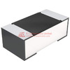
The YAGEO RC0402FR-07237KP is a surface mount thick film chip resistor offering 237 kOhms resistance with ±1% tolerance in the industry-standard 0402 (1005 metric) footprint. This component delivers 0.063W power dissipation capability while maintaining compact dimensions of 1.00mm × 0.50mm × 0.40mm, making it suitable for dense circuit board layouts where space optimization is required.
Built using thick film technology, this resistor provides reliable performance across a -55°C to 155°C operating temperature range with a temperature coefficient of ±100ppm/°C. The RC_P series construction ensures consistent electrical characteristics for precision analog circuits, voltage divider networks, and signal conditioning applications. With two terminations and 100% lead-free RoHS compliance rated as 7C1 without exemptions, the component meets current environmental regulations for commercial and industrial electronics manufacturing.
The 237 kOhm resistance value serves specific roles in biasing networks, feedback loops, and RC timing circuits where higher impedance is needed to minimize loading effects. The 1% tolerance specification supports applications requiring tighter resistance matching, such as differential pair networks, precision attenuators, and instrumentation front-end stages. The 1/16W power rating accommodates low-current signal paths commonly found in sensor interfaces, operational amplifier configurations, and CMOS logic pull-up/pull-down implementations.
This resistor's 0402 package format enables automated pick-and-place assembly with tape and reel packaging, supporting high-volume production requirements. The MSL 1 moisture sensitivity rating eliminates special handling procedures during PCB assembly, reducing manufacturing complexity and improving process reliability. Maximum seated height of 0.40mm maintains low profile requirements for applications with mechanical clearance constraints or stacked board assemblies.
The thick film construction provides stable resistance values under typical operating conditions while offering cost-effective manufacturing for volume production. The component's active product status and availability from YAGEO ensures supply chain continuity for ongoing product designs and field service requirements. With an EAR99 export classification and HTSUS code 8533.21.0030, the RC0402FR-07237KP integrates into standard procurement and logistics workflows for electronics manufacturers.
When a specific resistor model becomes unavailable during production ramp-up, or when design teams need to qualify secondary sources for supply chain resilience, identifying functionally equivalent components becomes necessary. The YAGEO RC0402FR-07237KP—a 237kΩ thick film resistor in 0402 package with 1% tolerance—represents a common precision bias resistor configuration in analog signal conditioning, feedback networks, and high-impedance sensing applications. Alternative part numbers from manufacturers including Vishay, Panasonic, Rohm, KOA Speer, and Bourns can serve as direct replacements when electrical, thermal, and mechanical parameters align with circuit requirements.
Direct alternatives include Vishay
CRCW0402237KFKED
, Panasonic
 CRCW0402237KFKED
Vishay Dale
RES SMD 237K OHM 1% 1/16W 0402
18207
ERJ-2RKF2373X
, Rohm ESR03EZPF2373, KOA Speer
 ERJ-2RKF2373X
Panasonic Electronic Components
RES SMD 237K OHM 1% 1/10W 0402
72999
RK73H1ETTP2373F
, and Bourns CR0402-FX-2373ELF. Each provides 237kΩ resistance in 0402 footprint with 1% tolerance and thick film construction, ensuring drop-in compatibility for most applications.
 RK73H1ETTP2373F
KOA Speer Electronics, Inc.
RES 237K OHM 1% 1/10W 0402
20000000

RC0402FR-07237KP (1)
Understanding the Original Specification Requirements
The RC0402FR-07237KP specification defines several parameters that establish functional boundaries for replacement selection. The 237kΩ resistance value with ±1% tolerance creates a 234.63kΩ to 239.37kΩ acceptable range, which directly impacts DC bias point accuracy in high-impedance circuits. The 1/16W power rating constrains maximum allowable voltage to approximately 122V RMS under steady-state conditions, assuming full power dissipation without derating.
Thick film construction provides cost-effective manufacturing while maintaining adequate long-term stability for most commercial applications. The ±100ppm/°C temperature coefficient translates to 23.7Ω/°C drift, representing 0.95kΩ total resistance change across the full -55°C to 155°C operating range. This drift characteristic becomes relevant in precision voltage dividers where temperature-induced ratio shifts affect output accuracy.
The 0402 package dimensions (1.00mm × 0.50mm × 0.40mm) establish PCB land pattern requirements and power dissipation capability through thermal contact area. Two terminations with standard nickel barrier/tin finish enable compatibility with both SnPb and lead-free solder processes. MSL-1 rating eliminates baking requirements before reflow, simplifying manufacturing logistics compared to moisture-sensitive devices.
Vishay CRCW0402237KFKED as Primary Replacement
Vishay's
CRCW0402237KFKED
matches all critical electrical specifications while offering equivalent manufacturing maturity and supply availability. The CRCW series employs ruthenium-based thick film technology identical to YAGEO's construction methodology, ensuring similar noise characteristics and voltage coefficient behavior. Resistance tolerance remains at ±1% across full production lots, maintaining interchangeability without circuit recalculation.
CRCW0402237KFKED
Vishay Dale
RES SMD 237K OHM 1% 1/16W 0402
18207
The temperature coefficient specification matches at ±100ppm/°C, producing identical thermal drift profiles in temperature-variant environments. Power dissipation capability extends to 0.063W at 70°C ambient with standard PCB mounting, equivalent to the original component. Operating temperature range spans -55°C to 155°C, covering automotive, industrial, and extended commercial requirements without derating.
Vishay's manufacturing process control delivers consistent resistance distribution and long-term stability characteristics comparable to YAGEO production. The part carries AEC-Q200 qualification when specified with automotive grade suffix, enabling use in safety-critical applications requiring formal reliability documentation. Tape and reel packaging follows EIA-481 standards with identical carrier tape dimensions, allowing direct feeder substitution on pick-and-place equipment.
Terminal metallurgy uses nickel barrier with matte tin finish, matching the original's solderability profile for both reflow and wave soldering processes. The 100% matte tin finish eliminates tin whisker growth concerns in long-life applications without requiring conformal coating. Electrical testing includes resistance measurement at 1V or less to avoid self-heating effects during production verification.
Panasonic ERJ-2RKF2373X for Enhanced Pulse Loading
The
ERJ-2RKF2373X
provides functional equivalence with improved pulse handling capability through Panasonic's optimized electrode geometry. While maintaining 237kΩ ±1% core specifications, this series features enhanced surge current withstand up to 2A for 10ms duration, beneficial in circuits experiencing transient conditions from inductive switching or ESD coupling paths.
ERJ-2RKF2373X
Panasonic Electronic Components
RES SMD 237K OHM 1% 1/10W 0402
72999
Temperature coefficient remains at ±100ppm/°C with resistance drift characteristics matching YAGEO's specification window. The 1/16W continuous power rating applies under standard thermal conditions, though Panasonic's internal resistive element design distributes thermal stress more uniformly across the substrate. This construction approach extends reliability in applications approaching maximum power dissipation limits.
Operating temperature range extends from -55°C to 155°C, maintaining full electrical specification compliance across automotive and industrial environments. The ERJ-2R series incorporates anti-sulfur resistor element formulation, preventing resistance drift in atmospheres containing sulfur compounds—relevant for devices deployed in industrial facilities or geothermal regions.
Package dimensions adhere to IEC 60115-8 standards for 0402 metric sizing, ensuring footprint compatibility with existing PCB layouts. Terminal plating uses three-layer structure with copper barrier and tin finish, optimized for lead-free solder profiles with peak temperatures up to 260°C. Moisture sensitivity level remains at MSL-1, eliminating storage constraints before assembly.
Rohm ESR03EZPF2373 for High-Density Applications
Rohm's ESR03EZPF2373 targets space-constrained designs through optimized terminal geometry that reduces minimum pad spacing requirements. The component maintains 237kΩ ±1% electrical specification while featuring reduced terminal height variation (±0.02mm) compared to standard 0402 construction, improving coplanarity for ultra-fine-pitch assembly.
Temperature coefficient specification matches at ±100ppm/°C, with resistance tracking characterized across full temperature range during production qualification. Power dissipation capability reaches 0.063W when mounted on standard FR-4 substrate with 1oz copper weight, equivalent to original component thermal performance. Operating range covers -55°C to 155°C, supporting extended commercial through automotive temperature grades.
Rohm's automated laser trimming process achieves tighter resistance distribution clustering within the ±1% tolerance band, reducing statistical variation in parallel or series resistor networks. This manufacturing control benefits precision voltage dividers where component matching affects overall circuit accuracy. The ESR03 series includes comprehensive reliability qualification data, including HTOL (High Temperature Operating Life) testing at 150°C for 1000 hours with
Terminal finish employs pure tin over nickel barrier, optimized for fine-pitch stencil printing without solder bridging during reflow. The component's low thermal mass reduces peak temperature differential during rapid heating cycles, minimizing stress on adjacent temperature-sensitive devices. MSL-1 rating eliminates baking procedures, maintaining throughput efficiency in high-volume manufacturing environments.
KOA Speer RK73H1ETTP2373F for Automotive Qualification
The
RK73H1ETTP2373F
addresses automotive supply chain requirements through comprehensive AEC-Q200 qualification and PPAP documentation support. While electrical specifications match at 237kΩ ±1% with ±100ppm/°C temperature coefficient, KOA Speer provides additional reliability data including moisture resistance testing per MIL-STD-202 Method 106, vibration testing per IEC 60068-2-6, and mechanical shock qualification per IEC 60068-2-27.
RK73H1ETTP2373F
KOA Speer Electronics, Inc.
RES 237K OHM 1% 1/10W 0402
20000000
Operating temperature range extends across -55°C to 155°C, meeting automotive Grade 2 requirements for passenger compartment and underhood non-engine applications. Power dissipation remains at 0.063W under standard mounting conditions, with derating curves provided for elevated ambient temperatures. The RK73H series incorporates anti-surge construction that withstands up to 1A pulse current for 5ms without permanent resistance shift.
Terminal metallurgy uses 100% matte tin finish over nickel barrier, eliminating lead content and providing tin whisker mitigation through grain structure control. Solderability testing follows J-STD-002 requirements with wetting force measurement, ensuring consistent solder joint formation across production lots. The component's thick film construction uses ruthenium-based resistive paste, matching industry-standard material composition.
KOA Speer maintains statistical process control data for resistance distribution, temperature coefficient clustering, and power rating consistency. This documentation supports APQP (Advanced Product Quality Planning) requirements in automotive qualification programs. Tape and reel packaging adheres to EIAJ standards with consistent component orientation for automated optical inspection verification.
Bourns CR0402-FX-2373ELF for Lead-Free Processing
Bourns' CR0402-FX-2373ELF specifically targets lead-free assembly environments through optimized terminal metallurgy and thermal cycle performance. The component maintains 237kΩ ±1% electrical specification with ±100ppm/°C temperature coefficient, while featuring enhanced resistance stability during multiple reflow exposures—critical for assemblies requiring rework or two-sided population.
Power dissipation capability reaches 0.063W at 70°C ambient, matching original component thermal characteristics. Operating temperature range spans -55°C to 155°C, covering commercial, industrial, and automotive environmental requirements. The CR series incorporates anti-sulfur resistive element formulation, preventing degradation in corrosive atmospheres containing sulfur dioxide or hydrogen sulfide.
Terminal plating uses 100% matte tin over copper-nickel barrier layers, optimized for
SAC305
(Sn96.5Ag3Cu0.5) lead-free solder alloy compatibility. The nickel barrier thickness exceeds 1.0μm, preventing copper migration into solder joints during thermal aging. Solderability performance meets J-STD-002D Category 3 requirements with consistent wetting force across production lots.
 SAC305
ALPHA
SAC305 AIPHA SMD
200000
Bourns provides comprehensive reliability qualification data, including temperature cycling per JESD22-A104 (-55°C to 125°C, 1000 cycles) with
Comparative Analysis of Alternative Solutions
Direct comparison reveals that all five alternatives meet core electrical requirements—237kΩ ±1%, 1/16W, ±100ppm/°C—ensuring functional compatibility in standard applications. Differences emerge in specialized performance characteristics that influence selection for specific use cases.
Vishay
CRCW0402237KFKED
provides the closest match to YAGEO's manufacturing process and material composition, making it the default choice for direct substitution without additional qualification testing. Panasonic
CRCW0402237KFKED
Vishay Dale
RES SMD 237K OHM 1% 1/16W 0402
18207
ERJ-2RKF2373X
offers superior pulse current handling (2A/10ms vs. typical 0.5A/5ms), beneficial in circuits exposed to inductive switching transients or ESD events.
ERJ-2RKF2373X
Panasonic Electronic Components
RES SMD 237K OHM 1% 1/10W 0402
72999
Rohm ESR03EZPF2373 features tighter coplanarity control (±0.02mm terminal height variation) compared to standard 0402 construction (±0.05mm typical), improving yield in ultra-fine-pitch assemblies. KOA Speer
RK73H1ETTP2373F
includes comprehensive automotive qualification documentation with AEC-Q200 and PPAP support, reducing qualification burden for automotive tier suppliers.
RK73H1ETTP2373F
KOA Speer Electronics, Inc.
RES 237K OHM 1% 1/10W 0402
20000000
Bourns CR0402-FX-2373ELF demonstrates enhanced thermal cycling reliability with
All alternatives maintain MSL-1 moisture sensitivity rating, eliminating storage and handling differences. Terminal metallurgy variations affect solder joint formation characteristics, though differences remain within acceptable ranges for standard SMT processing. Cost differences typically fall within 5-10% across manufacturers, making electrical and qualification requirements the primary selection drivers rather than piece-price optimization.
Validation Methods for Replacement Qualification
Using the Vishay
CRCW0402237KFKED
as qualification example, proper validation requires systematic verification across electrical, thermal, and mechanical parameters. Initial electrical characterization begins with resistance measurement using four-wire kelvin technique at 1V or less test voltage, eliminating lead resistance and avoiding self-heating effects that introduce measurement error in high-value resistors.
CRCW0402237KFKED
Vishay Dale
RES SMD 237K OHM 1% 1/16W 0402
18207
Thermal coefficient verification requires controlled temperature chamber testing across minimum three temperature points spanning the operational range. Resistance measurement at -55°C, 25°C, and 155°C establishes actual drift characteristic, confirming specification compliance and matching to original component behavior. Temperature stabilization time of 30 minutes minimum at each setpoint eliminates transient thermal gradients that corrupt measurements.
Power dissipation validation involves mounting components on representative PCB substrate with standard copper weight (1oz) and pad geometry matching production layout. Applying calculated power level (P = V²/R, or I²R depending on drive method) while monitoring case temperature with thermal imaging establishes actual thermal resistance. Surface temperature should remain below 155°C maximum rating with appropriate derating applied—typically 50% power at 70°C ambient for reliable operation.
Voltage coefficient measurement requires resistance characterization at multiple voltage levels (0.1V, 1V, 10V, 100V if circuit permits) to identify voltage-dependent resistance shift. Thick film resistors typically exhibit 100kΩ) may show increased sensitivity requiring verification. Measurement sequence should progress from low to high voltage, allowing thermal stabilization between steps to separate voltage coefficient from self-heating effects.
Solderability testing follows J-STD-002 wetting balance methodology, measuring wetting force and time-to-wet during controlled immersion in molten solder. Lead-free processing requires validation with
SAC305
alloy at 245°C ±5°C, with acceptable wetting force exceeding 0.5mN and time-to-wet under 2 seconds. Visual inspection after reflow should confirm uniform solder fillet formation without voids or dewetting.
SAC305
ALPHA
SAC305 AIPHA SMD
200000
Long-term stability assessment involves 1000-hour high-temperature storage at 155°C (HTSL - High Temperature Storage Life) followed by resistance measurement, with acceptable drift under ±0.5% for precision applications. Additional qualification may include temperature cycling (-55°C to 155°C, 500 cycles minimum) and humidity testing (85°C/85%RH, 1000 hours) depending on application environment and reliability requirements.
Decision Framework for Optimal Selection
For standard commercial applications requiring direct substitution without extended qualification, Vishay
CRCW0402237KFKED
provides the most straightforward replacement path through equivalent manufacturing methodology and material composition. Circuits operating in thermally stable environments with minimal transient exposure can transition to this alternative with basic electrical and solderability verification.
CRCW0402237KFKED
Vishay Dale
RES SMD 237K OHM 1% 1/16W 0402
18207
Applications experiencing repetitive pulse loading or ESD exposure benefit from Panasonic
ERJ-2RKF2373X
enhanced surge current capability, reducing failure risk in inductive switching circuits or interface protection networks. The anti-sulfur element construction adds reliability margin in industrial environments where atmospheric contamination may affect long-term stability.
ERJ-2RKF2373X
Panasonic Electronic Components
RES SMD 237K OHM 1% 1/10W 0402
72999
Ultra-high-density PCB layouts with fine-pitch component spacing should consider Rohm ESR03EZPF2373 for improved coplanarity control, reducing assembly defects from tombstoning or insufficient solder joint formation. The tighter dimensional control becomes relevant when 0402 component pitch approaches 0.6mm center-to-center spacing.
Automotive applications requiring formal qualification documentation and AEC-Q200 compliance should specify KOA Speer
RK73H1ETTP2373F
to minimize qualification testing burden. The comprehensive reliability data and PPAP support accelerate supplier approval processes in tier-level automotive supply chains.
RK73H1ETTP2373F
KOA Speer Electronics, Inc.
RES 237K OHM 1% 1/10W 0402
20000000
Products requiring multiple reflow cycles during assembly or anticipated field exposure to thermal cycling environments benefit from Bourns CR0402-FX-2373ELF enhanced thermal cycling performance. The improved resistance stability under thermal stress extends reliability in consumer electronics with repeated on-off cycling or automotive applications experiencing underhood temperature variations.


