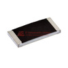
The Vishay Dale CRCW121827K0FKTK is a 27 kΩ thick film chip resistor designed for automotive and high-reliability applications requiring 1W power handling in a surface-mount package. This component delivers ±1% resistance tolerance with a temperature coefficient of ±100ppm/°C across an operating range from -55°C to 155°C, meeting AEC-Q200 qualification standards for automotive electronics.
Built in the 1218 (3246 Metric) package measuring 0.122" × 0.181" (3.10mm × 4.60mm) with a maximum seated height of 0.024" (0.60mm), this resistor provides enhanced power dissipation compared to smaller footprint alternatives while maintaining compatibility with automated pick-and-place assembly processes. The thick film construction offers reliable performance in current limiting, voltage division, and bias network applications where power density and thermal stability are design considerations.
The CRCW series architecture incorporates a two-terminal configuration optimized for pulse withstanding capability and long-term stability under automotive environmental stress conditions. The 1W power rating in this footprint enables operation at higher current levels than 0.5W resistors in similar applications, reducing the need for parallel resistor configurations or oversized components in power-sensitive circuits.
With AEC-Q200 qualification, this resistor addresses requirements in automotive power management, LED driver circuits, motor control systems, and battery management applications where extended temperature performance and qualification traceability are specified. The ±1% tolerance supports precision voltage reference circuits and feedback networks in switching regulators and linear power supplies without requiring component selection or trimming.
Available in tape and reel packaging with MSL-1 (Unlimited) moisture sensitivity classification, the CRCW121827K0FKTK simplifies inventory management and eliminates floor life restrictions during assembly operations. The component's RoHS non-compliant status should be verified against specific regional compliance requirements, while the REACH Affected designation indicates inclusion in SVHC monitoring protocols for supply chain documentation.
When a specific resistor model becomes difficult to source or when design requirements call for evaluation of alternative suppliers, identifying functionally compatible components becomes a practical engineering necessity. The CRCW121827K0FKTK from Vishay Dale—a 27 kOhm, 1%, 1W thick film resistor in 1218 package with AEC-Q200 qualification—serves in automotive and industrial applications where thermal stability, power handling, and qualification standards cannot be compromised. Direct replacements and functionally equivalent alternatives exist across multiple manufacturers, each offering varying degrees of electrical, thermal, and mechanical compatibility.
Alternative part numbers that may serve as replacements include Panasonic's ERJ-1WYJ273U, Yageo's RC1218FR-0727KL, KOA Speer's RK73HW3ATTD2702F, Bourns' CR1218-FX-2702ELF, and Rohm's MCR50JZHF2702. Each of these options provides the same nominal resistance value, tolerance class, and physical footprint, though differences in temperature coefficient, qualification status, and vendor-specific manufacturing processes warrant detailed comparison.

CRCW121827K0FKTK (1)
Understanding the Original Component Specifications
The CRCW121827K0FKTK belongs to Vishay Dale's CRCW series of thick film chip resistors designed for surface mount applications. Its 1218 footprint (3.10mm × 4.60mm) accommodates 1W continuous power dissipation at standard PCB mounting conditions. The ±1% tolerance and ±100ppm/°C temperature coefficient place this component in the precision resistor category, suitable for current sensing, voltage division, and feedback networks where drift affects circuit accuracy.
AEC-Q200 qualification indicates compliance with automotive reliability testing, including temperature cycling, moisture resistance, and operational life requirements. The -55°C to 155°C operating temperature range covers automotive underhood environments and industrial control applications. Thick film construction provides stability under electrical stress and maintains performance across the specified temperature extremes. The component carries Moisture Sensitivity Level 1 classification, requiring no special handling precautions during assembly.
The termination design follows standard end-cap configuration for reflow soldering compatibility. Rated power applies when mounted on a standard PCB with defined copper area for thermal dissipation. Actual power handling depends on ambient temperature, PCB thermal conductivity, and airflow conditions in the end application.
Panasonic ERJ-1WYJ273U as Direct Functional Equivalent
Panasonic's ERJ-1WYJ273U from the ERJ-1WY series provides matching electrical specifications across all parameters. The component delivers 27 kOhm resistance with ±1% tolerance and 1W power rating in an identical 1218 package. Temperature coefficient remains at ±100ppm/°C, and the operating temperature range spans -55°C to 155°C.
The ERJ-1WY series employs thick film ruthenium-based resistive element technology, similar to Vishay's approach. Terminal construction uses wraparound electrodes with nickel barrier and tin plating, ensuring consistent solderability. Panasonic specifies overload capability at 2.5× rated power for five seconds, providing protection during transient events.
Where the ERJ-1WYJ273U differs from the CRCW121827K0FKTK lies in qualification status. This Panasonic component follows automotive-grade manufacturing but does not carry explicit AEC-Q200 certification in standard catalog listings. For applications requiring documented qualification evidence, Panasonic offers the ERJ-P1WJ273U variant within the ERJ-P1W series, which includes full AEC-Q200 compliance documentation. The "P" designation specifically identifies automotive-qualified versions.
Thermal derating characteristics align with industry standard curves, where power handling reduces linearly above 70°C ambient to reach zero dissipation at maximum rated temperature. Pulse handling capability extends to 10× rated power for 10ms duration with 1% duty cycle, addressing inrush current scenarios in power supply and motor control circuits.
Yageo RC1218FR-0727KL Design Considerations
Yageo's RC1218FR-0727KL from the RC series presents identical electrical parameters: 27 kOhm resistance, ±1% tolerance, 1W power rating, and ±100ppm/°C temperature coefficient. Package dimensions match the standard 1218 footprint with compatible terminal geometry.
The RC series utilizes thick film technology with laser trimming for resistance value accuracy. Yageo's manufacturing process includes resistance drift testing per MIL-STD-202 Method 108, ensuring long-term stability. The component carries automotive qualification under AEC-Q200 Grade 1, supporting the full -55°C to 155°C range with documented reliability metrics.
Terminal metallization consists of silver/palladium/platinum conductor fired onto alumina substrate, with nickel barrier layer and pure tin outer plating. This construction provides lead-free reflow compatibility up to 260°C peak temperature with standard J-STD-020 profiles. Solderability testing follows J-STD-002 requirements with 95% minimum wetting coverage.
Voltage rating reaches 200V continuous, establishing safe operation margins in high-voltage signal paths. Pulse voltage withstand capability extends to 400V for transient suppression applications. The component's current noise specification remains below -20dB, making it suitable for precision analog circuits where Johnson noise affects measurement accuracy.
Yageo documents resistance change under rated load at less than ±0.5% after 1000 hours at maximum power and temperature. This load life stability metric confirms suitability for applications where resistance drift couples directly to output accuracy, such as precision current sources or reference voltage dividers.
KOA Speer RK73HW3ATTD2702F Automotive Implementation
The RK73HW3ATTD2702F from KOA Speer's RK73HW series maintains 27 kOhm resistance with ±1% tolerance in 1218 package format. Power rating holds at 1W with operating temperature from -55°C to 155°C. Temperature coefficient specification of ±100ppm/°C matches the reference component.
This series incorporates KOA Speer's automotive-grade thick film formulation with AEC-Q200 qualification covering all standard stress tests. The manufacturer provides lot-specific reliability data including high-temperature storage bake, temperature cycling, and moisture resistance test results. Failure rate documentation follows MIL-STD-690 calculation methodology.
Terminal structure employs wraparound electrode design extending onto the resistor body top surface, increasing mechanical attachment strength during thermal cycling. This construction reduces stress concentration at solder joints under coefficient of thermal expansion mismatch between component and PCB. The design addresses automotive vibration requirements per AEC-Q200-003 testing.
Resistance element architecture uses multi-layer glazing to isolate the ruthenium oxide film from environmental exposure. This protection layer enhances resistance to humidity ingress and maintains stability during temperature excursions. The component demonstrates less than ±0.25% resistance change after 1000-hour 85°C/85% RH storage per AEC-Q200-003.
Maximum working voltage reaches 200V DC continuous, with pulse withstand rated at 400V for 5 seconds. Dielectric withstand voltage between terminals and substrate exceeds 500V, providing isolation in high-voltage common-mode environments. The component meets automotive electromagnetic compatibility requirements for radiated and conducted emissions.
Bourns CR1218-FX-2702ELF Industrial Applications
Bourns' CR1218-FX-2702ELF from the CR1218 series offers 27 kOhm resistance with ±1% tolerance and 1W power rating. The component uses standard 1218 footprint with ±100ppm/°C temperature coefficient and -55°C to 155°C operating range.
The CR1218 series targets industrial and commercial applications rather than automotive qualification. While the component undergoes reliability testing including temperature cycling, high-temperature storage, and moisture resistance evaluation, it does not carry AEC-Q200 certification. This positions the part for cost-sensitive applications where automotive documentation requirements do not apply.
Construction follows thick film process with ruthenium-based resistive paste screen-printed onto alumina substrate. Terminal metallization uses silver conductor with nickel barrier and matte tin finish. The component meets RoHS compliance and carries halogen-free classification, addressing environmental requirements in commercial electronics.
Pulse handling capability extends to 5× rated power for 5 seconds with 0.1% duty cycle. Overload performance reaches 2× rated power for continuous operation with proportional temperature rise. These characteristics suit applications with periodic surge currents, such as relay coil damping or motor control snubber circuits.
Voltage coefficient specification remains below ±0.02% per volt change, ensuring resistance stability across varying bias conditions. This parameter becomes relevant in high-voltage signal conditioning where applied voltage affects effective resistance through self-heating or field-dependent mechanisms. Current noise index stays below -25dB, supporting low-noise analog front-end designs.
The component demonstrates ±0.5% maximum resistance change after 2000-hour life test at rated power and 70°C ambient. This endurance testing provides confidence for industrial applications with moderate reliability requirements and accessible service intervals.
Rohm MCR50JZHF2702 Compact Thermal Design
Rohm's MCR50JZHF2702 from the MCR series presents 27 kOhm resistance with ±1% tolerance in 1218 package. Power rating reaches 1W with ±100ppm/°C temperature coefficient and -55°C to 155°C operating temperature range. The component follows thick film construction with standard surface mount footprint.
The MCR series emphasizes thermal performance through optimized substrate material and terminal geometry. Rohm specifies thermal resistance from resistor element to solder point at 35°C/W, lower than typical values for 1218 package class. This characteristic enables operation closer to rated power limits in high ambient temperature environments.
Terminal design incorporates extended wraparound electrodes that increase solder joint area by approximately 15% compared to minimum specification footprints. The expanded contact area reduces thermal resistance from component to PCB while improving mechanical robustness under thermal cycling stress. This feature addresses applications with frequent temperature excursions or inadequate copper area for heat spreading.
The component carries automotive-grade process controls but does not specify AEC-Q200 qualification in standard documentation. Rohm offers automotive-qualified variants within the MCR series designated by suffix codes, requiring verification against specific part number requirements. For applications needing documented automotive compliance, explicit confirmation of qualification status becomes necessary.
Resistance tolerance distribution follows normal statistical pattern with typical values clustering within ±0.5% of nominal resistance. This tighter practical tolerance assists in applications where cumulative variation across multiple resistors affects circuit performance, such as precision voltage dividers or multi-element current sensing networks.
Voltage rating extends to 250V continuous, providing margin in circuits operating from rectified line voltage or high-voltage DC buses. The component withstands 500V dielectric test between terminals and ground plane, ensuring isolation integrity in switching power supply and motor drive applications.
Comparison Summary of Alternative Components
Each alternative component maintains the core electrical specifications required for functional replacement of the CRCW121827K0FKTK: 27 kOhm resistance, ±1% tolerance, 1W power rating, ±100ppm/°C temperature coefficient, and 1218 package footprint. Differences emerge in qualification status, vendor-specific manufacturing processes, and secondary parameters affecting application suitability.
The Panasonic ERJ-1WYJ273U matches all primary specifications but requires the ERJ-P1WJ273U variant for documented AEC-Q200 compliance. Yageo RC1218FR-0727KL provides automotive qualification with detailed reliability documentation and superior load life stability metrics. KOA Speer RK73HW3ATTD2702F emphasizes mechanical robustness through enhanced terminal structure, addressing vibration and thermal cycling environments.
Bourns CR1218-FX-2702ELF serves cost-sensitive industrial applications without automotive qualification requirements, offering standard reliability with simplified supply chain. Rohm MCR50JZHF2702 prioritizes thermal performance through reduced thermal resistance, benefiting designs with limited heat dissipation capability or high ambient temperatures.
Voltage ratings span from 200V to 250V continuous across the alternative components, with all options providing adequate margin for typical 27 kOhm resistor applications. Pulse handling capabilities vary from 2× to 10× rated power depending on duration and duty cycle specifications. Terminal metallization follows similar multi-layer plating structures across all manufacturers, ensuring reflow compatibility and solderability.
Temperature coefficient tolerance of ±100ppm/°C remains consistent across alternatives, resulting in maximum 0.27% resistance change over the full -55°C to 155°C operating range. This drift characteristic affects precision applications where temperature compensation or calibration must account for resistance variation. Actual drift typically follows more favorable curves than worst-case specification limits.
Practical Validation Methods for Replacement Implementation
Validating functional compatibility between the original CRCW121827K0FKTK and selected alternative components requires measurement of electrical parameters, thermal performance verification, and assessment of mechanical fit within the target assembly. Using the Yageo RC1218FR-0727KL as validation example demonstrates the practical approach applicable to any alternative component evaluation.
Initial electrical verification measures resistance at room temperature using four-wire measurement technique to eliminate lead resistance effects. The measurement setup should provide 1mV excitation or less to avoid self-heating during characterization. Measured resistance should fall within ±1% of 27 kOhm nominal value, confirming specification compliance. Additional measurements at temperature extremes validate temperature coefficient specification by comparing resistance at -55°C, 25°C, and 155°C.
Temperature coefficient validation proceeds by mounting the component on evaluation board with thermally controlled base plate. Resistance measurement at 25°C establishes baseline reference. The component temperature then steps to 155°C while monitoring resistance change. The observed resistance shift should remain below 1.3% for ±100ppm/°C specification over 130°C temperature span. Similarly, cooling to -55°C should produce resistance change not exceeding 0.8% from room temperature value. These measurements confirm that manufacturing process variation remains within specification limits and that temperature-induced drift matches design assumptions.
Power handling validation requires mounting the component on PCB with copper pad geometry matching the target application. Applied power steps from 25% to 50% to 75% to 100% rated power while monitoring component body temperature using thermocouple attached to package top surface or thermal imaging camera. At rated 1W dissipation with standard mounting conditions, component temperature rise should stabilize below 85°C above ambient, maintaining junction temperature below maximum rating. Thermal resistance calculation from measured temperature rise verifies that mounting implementation provides adequate heat dissipation path.
Pulse power testing applies repetitive pulses at energy levels corresponding to anticipated transient conditions in the target circuit. For applications with inrush current or switching transients, applying 5× rated power for 5-second duration followed by monitoring resistance change validates pulse handling capability. Resistance measured after pulse application should return to within ±0.1% of initial value, confirming that resistive element did not experience irreversible change from localized heating or stress.
Voltage coefficient verification applies increasing DC voltage across the resistor while measuring resistance change. With 100V applied across 27 kOhm resistor, current flow reaches approximately 3.7mA, well below power rating limits. Any resistance change exceeding 0.02% per volt indicates voltage-dependent behavior requiring assessment against circuit requirements. Most thick film resistors in this class demonstrate negligible voltage coefficient effects, but verification confirms assumption validity.
Solderability assessment follows standard reflow profile with peak temperature of 245°C for 5 seconds above 217°C liquidus temperature. Visual inspection after reflow confirms minimum 95% solder coverage on terminal surfaces. Cross-sectioning sample joints reveals solder penetration and wetting characteristics. Thermal cycling of assembled boards through -40°C to 125°C for 100 cycles with resistance monitoring during cycling identifies potential mechanical stress effects from coefficient of thermal expansion mismatch.
Long-term stability evaluation involves operating the component at rated power and maximum rated temperature for 168 hours minimum, with resistance measurements at 24-hour intervals. Resistance drift should remain monotonic without sudden shifts, and total change should stay within ±0.5% of initial value. This accelerated aging provides confidence that component will maintain stability through normal service life in target application.
Design Considerations for Cross-Manufacturer Replacement
Implementing alternative components from different manufacturers requires attention to specification interpretation differences, qualification documentation requirements, and supply chain management. While electrical parameters follow standardized definitions, test methods and acceptance criteria vary across manufacturers, affecting practical interchangeability.
Temperature coefficient specification of ±100ppm/°C represents maximum deviation over full temperature range, but actual drift follows manufacturer-specific curves that may exhibit different temperature dependencies. Some manufacturers specify temperature coefficient over two ranges (-55°C to 25°C and 25°C to 155°C), while others provide single-range specification. Comparing actual temperature drift curves from manufacturer datasheets reveals whether coefficient remains linear or exhibits higher-order temperature dependence affecting precision applications.
Automotive qualification status requires verification of specific test completion and documentation availability. AEC-Q200 compliance involves stress tests including temperature cycling, operational life, moisture resistance, and mechanical shock. Manufacturers may complete these tests but not explicitly certify compliance for all part numbers. Requesting qualification reports or certificates confirms that chosen alternative carries necessary documentation for automotive production requirements.
Power rating interpretation depends on mounting conditions specified by manufacturer. Standard rating typically assumes component mounted on defined PCB copper area with specified thickness and thermal conductivity. Applications with reduced copper area, inadequate thermal vias, or restricted airflow may require derating beyond datasheet curves. Thermal modeling or empirical temperature measurement validates that actual operating conditions remain within safe limits.
Tolerance distribution affects yield in circuits where multiple resistors interact to determine output accuracy. While ±1% tolerance establishes upper and lower specification limits, actual manufacturing distribution may center differently among manufacturers. Statistical process control data or incoming inspection measurements reveal whether particular manufacturer exhibits tighter practical tolerance or systematic offset requiring compensation in circuit design.
Moisture sensitivity level classification affects handling and storage requirements during assembly. All discussed alternatives carry MSL 1 rating, permitting unlimited floor life after package opening. This classification simplifies logistics compared to moisture-sensitive devices requiring baking or limited exposure time. Verification of MSL rating for specific purchase quantities ensures that handling procedures match device requirements.
Terminal finish composition influences solderability, whisker growth propensity, and long-term reliability. Pure tin finishes provide excellent solderability but may develop tin whiskers under mechanical stress or temperature cycling. Tin-lead finishes resist whisker formation but face restrictions in RoHS-compliant applications. Matte tin finishes balance these concerns and match across discussed alternatives, enabling consistent assembly processes.
Package marking and orientation features assist automated optical inspection and component verification during assembly. While 1218 package size accommodates visible part number marking, some manufacturers use abbreviated codes or orientation marks. Reviewing physical samples confirms that markings provide sufficient information for incoming inspection and traceability requirements in production environment.
Decision Framework for Optimal Replacement Selection
Selecting among alternative components depends on application-specific requirements balancing qualification needs, supply availability, cost constraints, and technical performance priorities. The decision framework progresses through qualification requirements, electrical specification verification, thermal performance assessment, and supply chain considerations.
For automotive applications requiring AEC-Q200 documentation, Yageo RC1218FR-0727KL and KOA Speer RK73HW3ATTD2702F provide explicit qualification with comprehensive reliability data. The Panasonic ERJ-P1WJ273U automotive variant serves this requirement when specified correctly, though standard ERJ-1WYJ273U requires confirmation of qualification status. Applications without automotive documentation needs gain flexibility to consider Bourns CR1218-FX-2702ELF as cost-effective option.
Designs operating near maximum power rating or in elevated ambient temperatures benefit from Rohm MCR50JZHF2702 due to lower thermal resistance specification. Applications with substantial PCB copper area and moderate operating power tolerate standard thermal performance from other alternatives without derating penalties. Thermal analysis of target operating conditions identifies whether thermal optimization provides tangible advantage.
Circuits sensitive to long-term resistance drift prioritize Yageo RC1218FR-0727KL based on superior load life stability documentation showing less than ±0.5% change after 1000 hours at rated conditions. Applications with periodic recalibration or less stringent accuracy requirements accept standard stability specifications common across alternatives.
Supply chain diversity and availability influence selection when component sourcing risk requires qualification of multiple suppliers. Establishing equivalency for components from multiple manufacturers enables flexible procurement responding to market availability fluctuations. The validation methods described earlier apply systematically across alternatives to build approved vendor list.
Cost optimization balances unit price against qualification expenses, testing requirements, and supply chain management overhead. While component pricing varies with market conditions and purchase volumes, automotive-qualified parts typically command premium over commercial-grade alternatives. Applications without automotive requirements achieve cost reduction through Bourns CR1218-FX-2702ELF or other industrial-grade options.
Technical documentation requirements affect selection when qualification reports, reliability predictions, or detailed test data must accompany component choice. Manufacturers vary in accessibility of technical support and willingness to provide detailed characterization data beyond standard datasheet specifications. Evaluating manufacturer responsiveness during component selection phase predicts support availability during production life cycle.