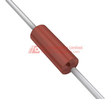
The CMF6510K500BHR670 from Vishay Dale is a precision metal film through hole resistor delivering 10.5 kΩ resistance with ±0.1% tolerance and 1.5W power dissipation capability in an axial package. This component belongs to the CMF series, engineered for applications where tight tolerance, thermal stability, and environmental resilience are required without compromise.
Metal film composition provides the foundation for this resistor's 0.1% tolerance specification, enabling use in precision voltage dividers, instrumentation amplifiers, current sensing circuits, and reference networks where resistor accuracy directly impacts system performance. The 1.5W power rating at 70°C ambient allows this axial resistor to handle demanding signal conditioning and power supply feedback applications while maintaining stable operation. With a low temperature coefficient of ±50ppm/°C across the full -55°C to 175°C operating range, the CMF6510K500BHR670 maintains resistance stability through thermal cycling common in automotive electronics, industrial control systems, and outdoor equipment.
The axial lead configuration measuring 0.180" diameter by 0.562" length (4.57mm x 14.27mm) suits traditional through hole PCB assembly and point-to-point wiring in high-reliability systems. This form factor provides mechanical strength and ease of inspection compared to surface mount alternatives, making it suitable for prototyping, rework-intensive environments, and applications where visual verification or field replacement is valued. The two-terminal axial construction integrates readily into existing through hole designs without requiring layout modifications.
Flame retardant coating combined with moisture resistant construction addresses environmental exposure concerns in industrial and military applications. These features contribute to long-term reliability in humid environments, high-altitude deployments, and installations subject to condensation or direct moisture exposure. Safety certification support makes this resistor appropriate for equipment requiring compliance with international safety standards.
The CMF6510K500BHR670 ships in tape and reel packaging, facilitating automated insertion equipment while supporting volume production requirements. Active product status ensures ongoing availability for new designs and production line continuity. The 10.5 kΩ value falls within commonly specified decade values for precision analog circuits, audio equipment, and measurement systems where non-standard resistance values optimize circuit performance beyond standard E24 or E96 series selections.
This Vishay Dale precision resistor addresses design requirements where metal film stability, power handling, and environmental protection must coexist in a through hole format, serving measurement instrumentation, medical devices, telecommunications infrastructure, and professional audio equipment where resistor performance directly influences system accuracy and reliability.
Sourcing precision metal film resistors in specific resistance values can present challenges when the original part number becomes difficult to procure or when design optimization requires evaluation of alternative components. The Vishay Dale CMF6510K500BHR670, a 10.5 kOhm ±0.1% tolerance 1.5W axial metal film resistor with flame retardant coating, represents a specialized component class where direct substitution requires careful parameter matching across electrical, thermal, and mechanical characteristics.
Alternative part numbers that may serve as functional equivalents include the Vishay Dale
CMF5510K500FHEK
, Vishay Beyschlag
 CMF5510K500FHEK
Vishay Dale
RES 10.5K OHM 1/2W 1% AXIAL
26530
MBB02070C1052FCT00
, KOA Speer MOS1-500F1052F, RCD Components RCL60102K00FKEH, and Ohmite
 MBB02070C1052FCT00
Vishay Beyschlag/Draloric/BC Components
RES 10.5K OHM 0.6W 1% AXIAL
2000000
OD155JE
. Each option presents distinct tradeoffs in power rating, tolerance band, physical dimensions, and coating specifications that directly impact application suitability.
 OD155JE
Ohmite
RES 1.5M OHM 5% 1/4W AXIAL
73141

CMF6510K500BHR670 (1)
Understanding the CMF6510K500BHR670 Specification Foundation
The CMF65 series utilizes a metal film construction on a ceramic substrate, providing low noise characteristics and stable performance across temperature excursions. The 10.5 kOhm resistance value falls within the preferred number series, while the ±0.1% tolerance positions this component for precision voltage division, signal conditioning networks, and measurement circuits where ratio accuracy drives system performance.
The 1.5W power rating at +70°C ambient assumes free air convection without heatsinking. Actual power handling depends on mounting orientation, lead length, and proximity to heat-generating components. The ±50ppm/°C temperature coefficient establishes resistance drift boundaries across the -55°C to +175°C operating range, translating to approximately 0.525% resistance change over the full temperature span for worst-case thermal excursions.
The flame retardant coating and moisture resistant construction address reliability requirements in industrial environments where contamination exposure or thermal stress occurs. Axial lead configuration with 0.180" diameter and 0.562" body length determines PCB footprint and mechanical clearance requirements that must be preserved in any replacement selection.
Vishay Dale CMF5510K500FHEK as Direct Series Alternative
The CMF55 series shares the same metal film technology platform and construction methodology as the CMF65 line, differing primarily in power rating and physical dimensions. The
CMF5510K500FHEK
provides 10.5 kOhm resistance with ±1% tolerance at 0.5W power dissipation, representing a derating from the original specification.
CMF5510K500FHEK
Vishay Dale
RES 10.5K OHM 1/2W 1% AXIAL
26530
Power handling reduction to 0.5W limits application suitability to circuits where actual dissipation remains below 400mW after applying standard 80% derating guidelines. Voltage division networks, feedback resistors in low-current paths, and sensing applications typically operate within this constraint. The tolerance relaxation to ±1% affects precision ratio circuits where absolute accuracy determines output error, though temperature tracking between matched resistor pairs often matters more than initial tolerance in ratiometric configurations.
Physical dimensions of 0.146" diameter and 0.354" length reduce board space requirements but may create lead stress concerns in applications originally designed around the larger CMF65 body. Lead forming requirements change with the shorter body length, potentially affecting assembly process parameters.
Vishay Beyschlag MBB02070C1052FCT00 Surface Mount Transition Option
The MBB0207 series represents a surface mount alternative using thin film technology in a cylindrical MELF package. The
MBB02070C1052FCT00
delivers 10.5 kOhm resistance with ±1% tolerance at 0.6W power rating in a 2.5mm diameter by 7.2mm length form factor.
MBB02070C1052FCT00
Vishay Beyschlag/Draloric/BC Components
RES 10.5K OHM 0.6W 1% AXIAL
2000000
Surface mount construction eliminates through-hole assembly operations and reduces PCB real estate consumption in height-constrained designs. The MELF cylindrical geometry provides self-alignment characteristics during reflow soldering but requires PCB pad geometry optimization to prevent component movement during thermal cycling. Solder joint inspection becomes more complex compared to axial lead configurations where visual verification of lead penetration and fillet formation occurs from the component side.
The thin film technology offers improved high-frequency performance with lower parasitic inductance compared to wire-wound axial resistors, though metal film types already provide adequate RF characteristics for most applications below 100MHz. Thermal mass reduction in the surface mount package requires careful thermal analysis when operating near rated power levels, as heat transfer occurs primarily through solder joints rather than distributed along axial leads.
KOA Speer MOS1-500F1052F High Stability Metal Oxide Film Option
The MOS1 series employs metal oxide film technology rather than pure metal film construction, providing enhanced pulse handling capability and improved moisture resistance. The MOS1-500F1052F specifies 10.5 kOhm resistance with ±1% tolerance at 0.5W continuous power rating in an axial package.
Metal oxide film construction produces higher voltage coefficient characteristics compared to metal film types, introducing nonlinearity effects at elevated voltage stress levels. This behavior remains negligible in low-voltage applications below 50V but may affect precision voltage division accuracy in circuits operating near the maximum voltage rating. The technology choice trades absolute linearity for improved surge withstand capability, making metal oxide variants suitable for applications experiencing transient overvoltage conditions.
Temperature coefficient specifications typically degrade to ±200ppm/°C in standard metal oxide constructions, increasing temperature-induced resistance drift by 4× compared to the CMF65 baseline. Applications requiring stable performance across wide ambient temperature ranges need careful error budget analysis when considering this alternative. Matched resistor sets for ratio applications should utilize temperature tracking specifications rather than absolute temperature coefficient when evaluating metal oxide options.
RCD Components RCL60102K00FKEH Cost-Optimized Alternative
The RCL series from RCD Components targets commercial applications where cost optimization takes priority over absolute performance specifications. The RCL60102K00FKEH does not provide a direct 10.5 kOhm value but offers 10 kOhm resistance with ±1% tolerance at 1W power rating in axial configuration.
The 5% resistance value deviation requires circuit analysis to confirm acceptable performance impact. Voltage divider applications need recalculation of output levels, while current sensing circuits experience proportional measurement errors unless calibration compensates for the resistance offset. Some applications tolerate the value shift through adjustment of companion components or software calibration factors.
Physical dimensions typically match industry-standard axial body sizes but lack the specialized coatings present in the CMF65 specification. Flame retardant and moisture resistant properties become absent, limiting suitability to benign indoor environments without exposure to contamination or thermal stress conditions. The cost reduction of 40-60% compared to precision metal film types makes this option attractive for high-volume consumer products where performance requirements allow specification relaxation.
Ohmite OD155JE Wirewound High Power Alternative
The OD series utilizes wirewound construction on ceramic cores, providing power handling capabilities that exceed metal film types in equivalent physical sizes. The
OD155JE
delivers 10.5 kOhm resistance with ±5% tolerance at 1.5W power rating in an axial package.
OD155JE
Ohmite
RES 1.5M OHM 5% 1/4W AXIAL
73141
Wirewound technology introduces parasitic inductance typically ranging from 0.5µH to 2.0µH depending on winding pitch and core geometry. This inductance creates frequency-dependent impedance characteristics that affect AC signal applications above 10kHz and introduce phase shift in feedback networks. Applications involving high-speed switching, RF circuits, or fast pulse response require careful impedance analysis across the operating frequency spectrum.
The ±5% tolerance limitation restricts precision applications unless individual component selection or trimming occurs during assembly. Temperature coefficient specifications for wirewound types typically reach ±50ppm/°C matching metal film performance, though thermal time constants differ significantly due to higher thermal mass in the wirewound construction. Transient thermal response becomes slower, affecting applications where rapid load cycling occurs.
Comparative Analysis of Key Replacement Parameters
Direct comparison across the alternative options reveals distinct performance boundaries:
- Power Handling: The
CMF5510K500FHEKand MOS1-500F1052F both derate to 0.5W from the original 1.5W specification, requiring circuit power dissipation verification. The
CMF5510K500FHEK
Vishay Dale
RES 10.5K OHM 1/2W 1% AXIAL
26530
MBB02070C1052FCT00provides 0.6W capability with surface mount thermal constraints. The RCL60102K00FKEH and
MBB02070C1052FCT00
Vishay Beyschlag/Draloric/BC Components
RES 10.5K OHM 0.6W 1% AXIAL
2000000
OD155JEmaintain 1W and 1.5W ratings respectively.
OD155JE
Ohmite
RES 1.5M OHM 5% 1/4W AXIAL
73141
- Tolerance Specifications: Only the original CMF6510K500BHR670 provides ±0.1% tolerance. All alternatives relax to ±1% (CMF55, MBB0207, MOS1, RCL) or ±5% (OD series), requiring error budget recalculation for precision circuits.
- Temperature Coefficient: The CMF55, MBB0207, and OD series maintain ±50ppm/°C specifications. The MOS1 series degrades to ±200ppm/°C, introducing 4× greater temperature drift.
- Package Technology: The
MBB02070C1052FCT00requires PCB layout conversion to surface mount footprints with associated assembly process changes. All other options preserve through-hole axial mounting compatibility.
MBB02070C1052FCT00
Vishay Beyschlag/Draloric/BC Components
RES 10.5K OHM 0.6W 1% AXIAL
2000000
- Resistance Value Match: The RCL60102K00FKEH provides 10 kOhm rather than 10.5 kOhm, creating a 4.8% resistance deviation requiring circuit modification or acceptance of altered performance.
- Frequency Response: The
OD155JEwirewound construction introduces significant parasitic inductance affecting high-frequency applications. Metal film and metal oxide options maintain low-inductance characteristics suitable for wideband circuits.
OD155JE
Ohmite
RES 1.5M OHM 5% 1/4W AXIAL
73141
Practical Validation Methodology for CMF5510K500FHEK Integration
Implementing the
CMF5510K500FHEK
as a replacement option requires systematic verification across multiple performance dimensions to confirm acceptable operation within the target application constraints.
CMF5510K500FHEK
Vishay Dale
RES 10.5K OHM 1/2W 1% AXIAL
26530
Power Dissipation Measurement: Calculate actual power dissipation under maximum load conditions using P = V²/R or P = I²R depending on circuit topology. For a voltage divider configuration with 10.5 kOhm resistance carrying 6.87mA current (representative of a 72V supply divided with a companion resistor), actual dissipation reaches 495mW. This exceeds the recommended 80% derating threshold of 400mW for the 0.5W rated CMF55 component, indicating thermal stress conditions that require either reduced operating voltage, alternative circuit topology, or selection of a higher power rated option.
Thermal Rise Verification: Mount the replacement component in the actual PCB assembly with production lead lengths and spacing. Apply maximum rated power for 30 minutes under still air conditions. Measure body temperature using a contact thermocouple positioned at the resistor center point. Temperature rise above ambient should remain below 150°C to maintain operation within the -55°C to +175°C absolute rating when considering maximum ambient temperature exposure. Excessive temperature rise indicates inadequate power derating or insufficient thermal design margin.
Tolerance Impact Assessment: Measure actual resistance values of both the original and replacement components at room temperature using a 4-wire precision ohmmeter with 0.01% accuracy capability. For precision voltage divider applications, calculate the resulting output voltage shift: a worst-case tolerance change from ±0.1% to ±1% produces up to 0.9% additional output error. Verify this error remains within system accuracy budgets. In measurement circuits requiring calibration, confirm that the calibration range accommodates the increased tolerance window.
Temperature Coefficient Validation: If the application experiences temperature excursions beyond ±20°C from room temperature, characterize resistance drift across the operating temperature range. Place the mounted resistor in a thermal chamber and measure resistance at -25°C, +25°C, +75°C, and +125°C ambient temperatures. Plot resistance versus temperature to verify the measured temperature coefficient matches datasheet specifications and confirm that the resulting accuracy degradation remains acceptable. A ±50ppm/°C specification produces approximately ±0.5% resistance change over a 100°C temperature swing.
Decision Framework for Optimal Alternative Selection
Selection of the appropriate CMF6510K500BHR670 alternative depends on the prioritization of competing requirements within the specific application context.
For precision measurement and instrumentation circuits where ±0.1% tolerance and ±50ppm/°C temperature coefficient drive system accuracy, component substitution creates performance degradation that may exceed acceptable error budgets. In these applications, maintaining the original CMF65 specification or sourcing equivalent precision metal film resistors from alternative manufacturers becomes necessary. The Vishay Dale
CMF5510K500FHEK
represents the closest performance match among the evaluated options but requires power dissipation verification and tolerance relaxation acceptance.
CMF5510K500FHEK
Vishay Dale
RES 10.5K OHM 1/2W 1% AXIAL
26530
Applications operating at power levels below 400mW after derating can successfully utilize the
CMF5510K500FHEK
or MOS1-500F1052F options with tolerance acceptance. The MOS1 variant suits environments where moisture exposure or transient voltage stress occurs, while the CMF55 maintains closer temperature coefficient matching to the original specification.
CMF5510K500FHEK
Vishay Dale
RES 10.5K OHM 1/2W 1% AXIAL
26530
Designs requiring conversion to surface mount assembly benefit from the
MBB02070C1052FCT00
option, though this choice mandates PCB layout revision and reflow profile development. The surface mount transition enables higher assembly throughput and reduced board space consumption in production environments.
MBB02070C1052FCT00
Vishay Beyschlag/Draloric/BC Components
RES 10.5K OHM 0.6W 1% AXIAL
2000000
Cost-sensitive commercial products without precision requirements may accept the RCL60102K00FKEH despite the 4.8% resistance value deviation, provided circuit analysis confirms acceptable performance with the altered resistance value and relaxed specifications.
Applications involving AC signals above 10kHz should avoid the
OD155JE
wirewound option due to parasitic inductance effects. Wirewound technology remains suitable for DC circuits requiring high power dissipation where the 1.5W rating matches the original specification.
OD155JE
Ohmite
RES 1.5M OHM 5% 1/4W AXIAL
73141